Alternating current is one of the most important topics in Class 12 Physics because it explains how electrical energy is generated, transmitted and used in everyday devices. In alternating current circuits, voltage and current continuously change with time and follow a sinusoidal pattern. To understand this behaviour more clearly, physicists use a graphical method known as the rotating vector or phasor representation. This method helps students visualise how alternating voltage and current vary and how phase differences appear in electrical circuits.
I am writing about this topic because many students feel confused when they first study alternating current equations. The formulas may look straightforward, but understanding what they represent physically often becomes difficult. From my experience, once students understand the idea of rotating vectors and phase relationships, the behaviour of alternating current becomes much easier to interpret. This concept also builds a strong foundation for analysing more advanced AC circuits involving resistors, inductors and capacitors.
Understanding Alternating Voltage and Current
Alternating voltage and current change continuously with time and follow a sinusoidal pattern. The instantaneous value of alternating voltage can be written as
V = V₀ sin(ωt)
Here:
- V₀ is the peak value of voltage
- ω is the angular frequency
- t represents time
This expression shows that the voltage gradually increases from zero to a maximum value, then decreases and reverses direction during each cycle.
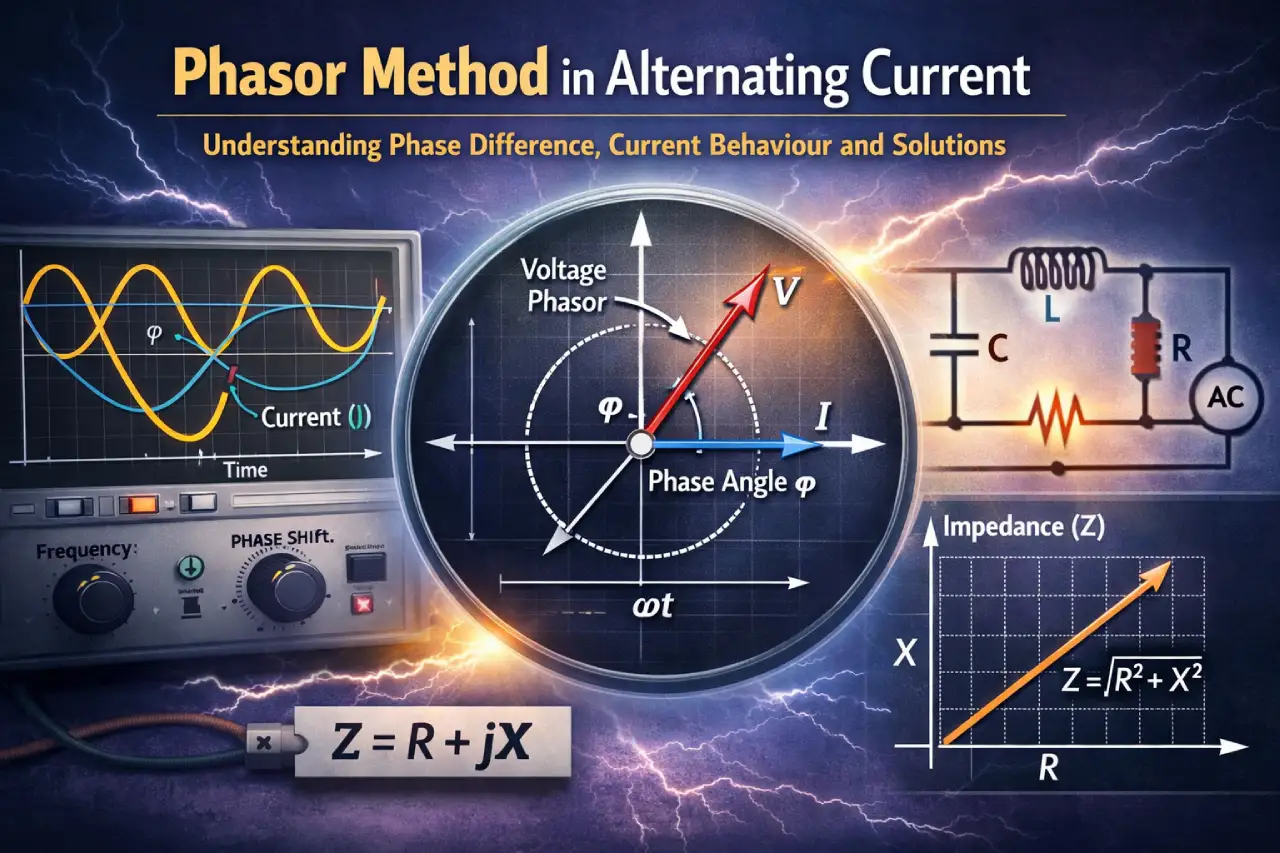
What Is a Rotating Vector?
A rotating vector is a graphical representation used to describe alternating quantities. The vector rotates with constant angular velocity, and its projection on a reference axis gives the instantaneous value of the alternating voltage or current.
Important characteristics of rotating vectors include:
- The length of the vector represents the maximum value of the AC quantity
- The angle of rotation represents the phase of the quantity
- The projection on the axis gives the instantaneous value of voltage or current
Because of this representation, rotating vectors are commonly called phasors.
Phase Difference in AC Circuits
Phase difference describes how much one alternating quantity leads or lags behind another. It represents the angular separation between the voltage and current waveforms.
Different circuit elements influence the phase relationship in different ways:
- In some circuits, voltage and current reach their peaks at the same instant.
- In others, one quantity reaches its peak before the other.
Understanding this phase relationship is important when analysing alternating current circuits.
Behaviour in a Pure Resistive Circuit
In a circuit that contains only resistance, the behaviour of alternating current is quite simple.
Key observations include:
- Voltage and current remain in phase
- Both reach maximum and minimum values at the same time
- Electrical energy is converted into heat within the resistor
This is the simplest example of an alternating current circuit.
Download this Alternating Current WS 2 sol PDF File: Click Here
Behaviour in Inductive Circuits
When inductance is present in a circuit, the situation changes. An inductor resists changes in current by generating an induced electromotive force.
As a result:
- Current lags behind the applied voltage
- A phase difference appears between voltage and current
This behaviour occurs because energy is temporarily stored in the magnetic field produced by the inductor.
Behaviour in Capacitive Circuits
A capacitor affects alternating current circuits in a different way.
In capacitive circuits:
- Current leads the voltage
- Electrical energy is stored in an electric field
During each cycle, the capacitor stores energy in one half of the cycle and releases it during the other half.
Average Value of Alternating Current
A full cycle of alternating current consists of two halves:
- A positive half cycle
- A negative half cycle
Since the current flows in opposite directions during these two halves, the average value of alternating current over a complete cycle becomes zero.
This is why instruments designed to measure direct current cannot measure alternating current directly.
Generation of Alternating EMF
Alternating voltage can also be generated by rotating a coil in a magnetic field. When a coil rotates inside a magnetic field, the magnetic flux linked with the coil changes continuously. This change in magnetic flux produces an induced electromotive force according to electromagnetic induction.
The magnitude of the induced emf depends on factors such as:
- Number of turns in the coil
- Area of the coil
- Strength of the magnetic field
- Speed of rotation
This principle is used in electrical generators to produce alternating current.
Why Phasor Representation Is Useful
The rotating vector method provides a simple and powerful way to analyse alternating current circuits.
It helps students:
- Visualise how voltage and current change with time
- Understand phase differences clearly
- Analyse circuits containing resistors, inductors and capacitors
- Simplify calculations in AC circuit problems
Because of these advantages, phasor diagrams are widely used in both physics and electrical engineering.