Alternating current circuits are often analysed using sinusoidal equations, but understanding how voltage and current vary with time can become complicated when dealing with different circuit components. To make the analysis easier, physicists use a graphical method called the rotating vector or phasor representation. This method represents alternating voltage and current as rotating vectors, making it easier to understand how these quantities change with time and how phase differences arise in electrical circuits.
I am writing about this topic because many students struggle to visualise the relationship between voltage and current in alternating current circuits. While the formulas are easy to memorise, the real understanding comes from seeing how these quantities behave graphically. In my experience, once the concept of rotating vectors is understood, analysing AC circuits becomes much clearer. This approach helps students interpret phase relationships and understand how different electrical components influence the behaviour of alternating current.
Understanding Alternating Current and Sinusoidal Variation
Alternating current is a type of electric current whose magnitude and direction change periodically with time. Unlike direct current, which flows steadily in one direction, alternating current reverses its direction after regular intervals.
The instantaneous value of alternating current or voltage is commonly expressed using a sinusoidal equation:
V = V₀ sin(ωt)
Where:
- V₀ represents the peak value of voltage
- ω represents the angular frequency
- t represents time
This equation shows that the value of voltage or current changes continuously as time progresses.
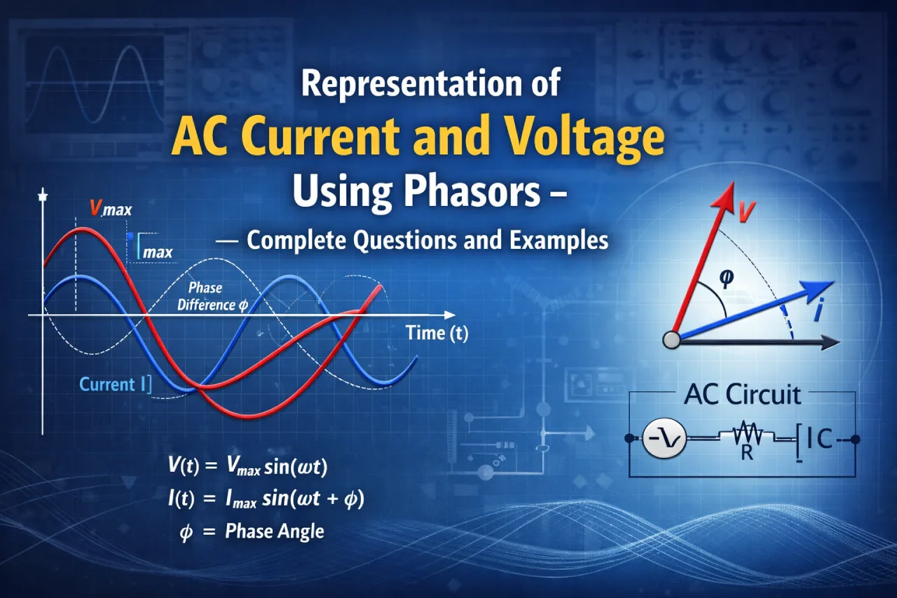
What Is a Rotating Vector?
A rotating vector is a graphical representation used to describe alternating quantities. The vector rotates with a constant angular speed and its projection on a vertical axis gives the instantaneous value of the alternating voltage or current.
Important characteristics of a rotating vector include:
- The length of the vector represents the amplitude of the AC quantity.
- The angle of rotation represents the phase of the quantity.
- The projection on the axis gives the instantaneous value.
This rotating vector is commonly called a phasor.
Phase Difference in AC Circuits
One of the most important aspects of alternating current circuits is the phase relationship between voltage and current. The phase difference depends on the type of component present in the circuit.
Pure Resistive Circuit
In a circuit that contains only resistance:
- Current and voltage remain in phase
- Their peaks occur at the same instant
- Electrical energy is converted into heat in the resistor
This is the simplest type of alternating current circuit.
Pure Inductive Circuit
In a circuit containing only an inductor:
- Current lags behind the applied voltage
- The phase difference between voltage and current is 90 degrees
This occurs because the inductor resists changes in current by inducing an opposing electromotive force.
Pure Capacitive Circuit
In a circuit containing only a capacitor:
- Current leads the voltage
- The phase difference is also 90 degrees
The capacitor stores electrical energy in the form of an electric field and releases it during the cycle.
Download this Alternating Current WS 2 PDF File: Click Here
Phasor Diagrams and Their Importance
Phasor diagrams are graphical tools used to represent alternating voltage and current in a circuit. In these diagrams, rotating vectors represent different electrical quantities.
Phasor diagrams help in:
- Visualising the phase difference between voltage and current
- Determining the resultant voltage in complex circuits
- Simplifying calculations in AC circuit analysis
Because of this advantage, phasor diagrams are widely used in electrical engineering and physics.
Energy Behaviour in Different AC Components
Different components in an AC circuit interact with electrical energy in different ways.
Resistors
- Convert electrical energy into heat
- Consume power continuously
Inductors
- Store energy in a magnetic field
- Return energy back to the circuit
Capacitors
- Store energy in an electric field
- Release energy during the cycle
Over a complete cycle, inductors and capacitors do not consume net energy from the power source.
Practical Importance of Rotating Vector Representation
The rotating vector method is extremely useful for analysing alternating current circuits.
It helps students and engineers:
- Understand phase relationships clearly
- Analyse circuits containing resistors, capacitors and inductors
- Determine voltage and current relationships in AC systems
- Simplify the study of complex electrical circuits
Because of its visual nature, this method makes AC circuit analysis much easier to understand.